I need to test my Commodore 64 but I have no floppy drive, cassette deck or cartridge…
This was the dilemma I had one evening after repairing my newly acquired Commodore 64 machine – yes I will write a blog entry about it and link it here later. I really wanted to load a game and test the famous SID chip for it’s sound quality. So off to Google looking for quick solution. There are plenty of those floating around, most are semi-commercial, and pretty complicated and/or expensive, not something you can implement “tonight”. Than I came across the Pi1541 by Steve White. According to his post “Pi1541 is a real-time, cycle exact, Commodore 1541 disk drive emulator that can run on a Raspberry Pi 3B (or 3B+). The software is free and I have endeavored to make the hardware as simple and inexpensive as possible“. Wow, amazing work Steve! Plus he released it all to public for free, including schematic diagram of the “cable” and the source code of his software.
If you follow his post, in his setup instructions you will get to step six where you need to create the cable. There are two versions, simple and more complex. Most of us need the simple version, if fact when you read the instructions you will soon realize the that you can make a “super simple” version of the simple one as there are quite a few “optional” components. So to make the task easy I’ve created a new modified diagram of the “super simple Pi1541 cable”:

Full size image here
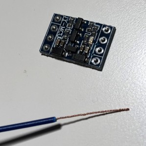
Yep, that’s it, one component – the 4 channel logic level converter, Steve suggests the Sparkfun part number, but places like eBay, Amazon, Banggood are full of alternatives. All you need is one based on MOS-FET transistors (you will see 4 of the 3 legged tiny transistors on the board) and you’re good to go.
If you want to know what the logic converter does, it’s simple: you can connect to each other 4 digital lines of signals that are not compatible from the logic level point of view – the raspberry pi uses 0V/3.3V voltage to it’s logic “0” and “1” and the Commodore uses 0V/5V voltage. Each pair of HV1/LV1, HV2/LV2, HV3/LV3, HV4/LV4 handles one line, you can imagine that for each pair HV1 pin and the LV1 are “connected” to each other, so if we send a 3.3V “signal” into LV1, it will come out of HV1 as 5V “signal” (note: this conversion works in both directions). The remaining connections are related to power, so you feed “ground” to the GND pins (note: GND pin on the LV side is directly connected to GND on the HV side), you feed the low supply voltage to “LV” pin and the high supply voltage to “HV” pin.
I had one of the Sparkfun parts in my drawer so I decided to go ahead and build the simplified version of the cable, here is what I’ve done:
Step 1.
You need to somehow get the signals out of the Commodore and into the logic converter:
Option A: Get a DIN 6 plug and solder 5 wires onto it, this is what I’ve done:
“But you promised no soldering”, okay….
Option B: you could “sacrifice” a spare serial cable that you use to connect the original 1541 drive to your Commodore 64, cut it half use one half for your cable and give the there half to one of your friends so they can create a cable for themselves 🙂
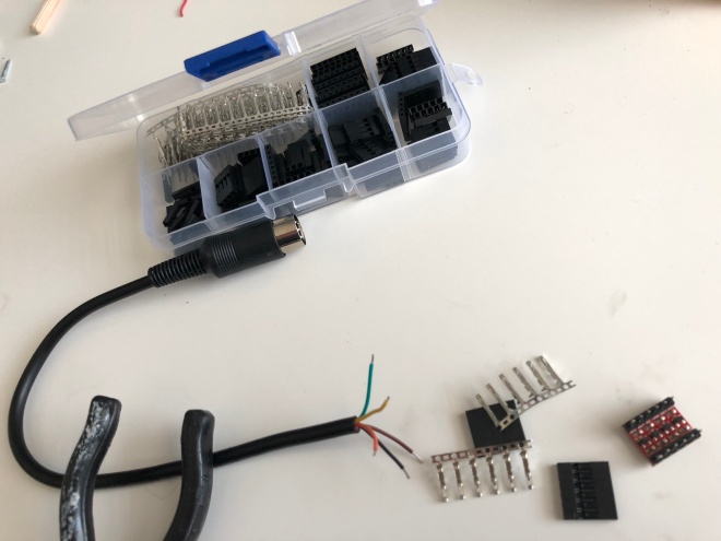
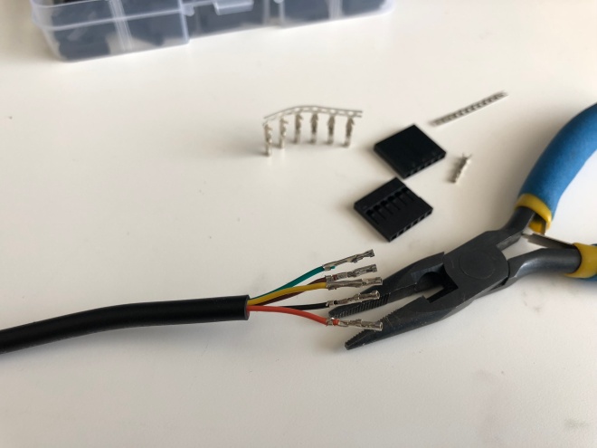
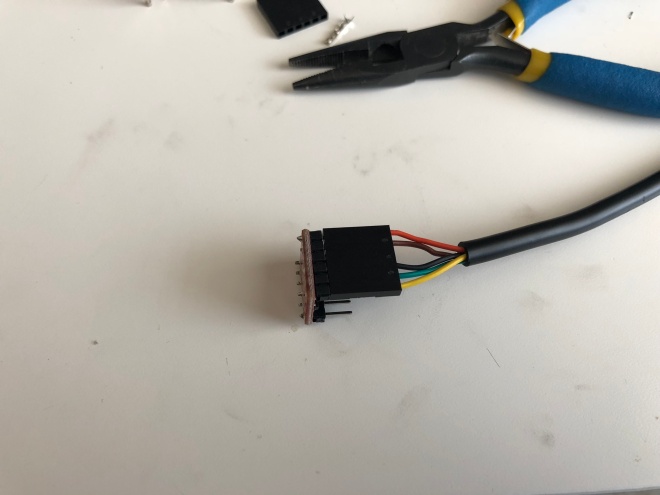
Step 2.
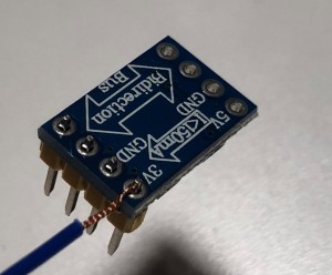
You need to somehow connect the cable to the logic level converter, again many options, I soldered a pin header to the logic converter, “crimped” the connectors and used a 6 way plastic plug like this:
“But you promised no soldering”, okay….
Option B. You could simply twist the cable into the holes of the logic converter, here is an example of how I would do it if I didn’t know how to solder (example shows different logic converter as I don’t have the 4 channel one handy that doesn’t have pins soldered already):

Step 3.
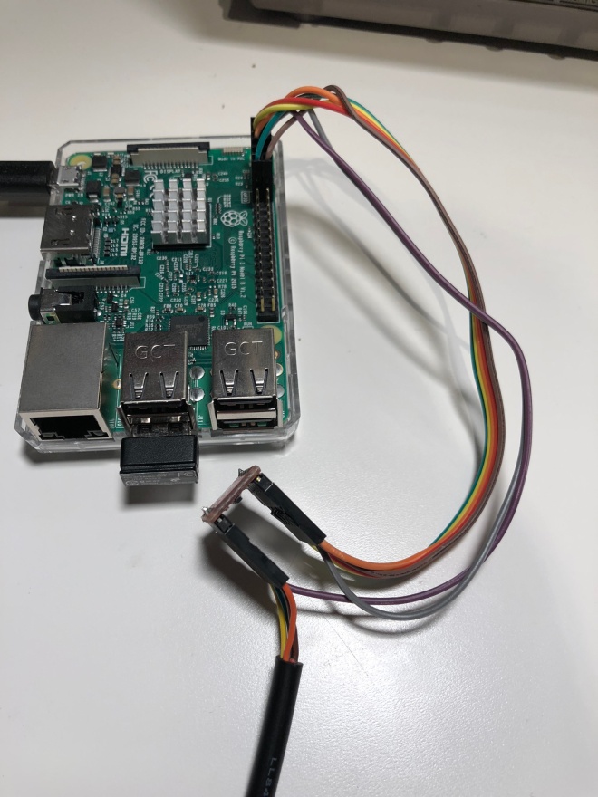
Option A. Now we need to deal with the connections from the logic converter to the raspberry pi. In my case I had the pins already soldered on my logic converter so I crimped another 7 connections between the logic converter and raspberry pi:
But, but….
Option B. Since raspberry pi comes with pin headers soldered in already you have no choice you need to “source” the raspberry pi side connectors from somewhere – a good source would be and old computer case that has cables for DISK LED, POWER LED, RESET, BUZZER etc. This will give you the “plug” on the raspberry pi side, on the logic level converter side use the “twist” method mentioned above. Wire everything as per the simplified diagram.
Step 4.
Tidy up. I secured my headers and the converter PCB with some paper tape

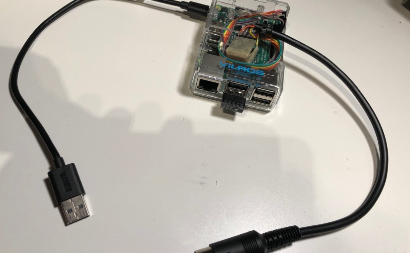
And finally I placed the pi and the converter cable in a raspberry pi case:

Now the only other thing left is to prepare the SD card.
Step 5.
To prepare the SD card, just follow Steve’s instructions. You should end up with SD card structured like this:
/
/bootcode.bin
/config.txt
/dos1541
/fixup.dat
/kernel.img
/options.txt
/start.elf
/1541/
/1541/fb64
/1541/Games/mygamefile1.d64
The first file in the 1541 folder should the the “file browser” file compatible with your platform, in my case I’m using Commodore 64 so I only left the “fb64” file in that folder. This file needs to be the first file in that folder so that when you boot your Commdore and issue the famous <LOAD “*”,8> command the file browser will start and let you “browse” the content of your virtual 1541 disk. To keep the file first I added the Games folder and placed all my games files inside it.
Step 6.
Donate or support Steve via PayPal/Patreon to reward his hard work 🙂

I wish parallel port/Dolphin Dos emulation would also be supported!
LikeLike
Thanks for this, I am totaly amazed about this being develloped and working, I have now every game ever written for the C64 on 1 SD card available on this diskdrive emulator, life is not getting any better than this !
LikeLike
Hi! just arrived to your post when noticed that the SW1.. SW2.. were “optional” in the “simplest version of the hardware” on the cbm-pi1541 page. Yours is really the most simple 🙂
I understood everything but the only thing I don’t understand is: the cable that gets out of the pi 3.3V (1) is getting back converted as 5V (2) –> is this in order to “power” the pi? Best!
LikeLike
Hey Javier. Thanks for taking the time to comment. My diagram is really the simplest implementation, and this was the main reason I decided to share it with everyone in the post.
In regards to the part you were not sure about, both 3.3V and 5V are going from the raspberry pi to the logic level converter and are required for the converter to operate correctly. You still need to provide the 5V power to the raspberry pi separately.
LikeLike
What cable do you use. I can buy the 6Din, logic converter and bit on eBay but wasn’t sure which cable to buy.
LikeLike
Not sure what cable are you talking about, but for the cable between the logic converter and the raspberry Pi you could re-use a 6pin din to 6pin din straight-through cable “chopped” in half like I suggested in the article. The approach is different mainly based on you having access to soldering iron or not 🙂
LikeLike
Love these simple instructions. I have an original Raspberry Pi 1 lying around but before I go shopping for the components, do you think it will work on one? I think it should be ok for the GPIO connections but not sure about the software. I’ll also be trying this on a Vic-20 …
LikeLike
Thanks for the comment Steve. In terms of the Raspberry Pi 1, unfortunalty this will not work. To get the emulation perfectly working, the firmware needs full performance of at least Pi 3B (you can also use the 3B+). The good news is that with the release of Pi4 a lot of people are getting rid of the 3 version, so you can pick one up much cheaper than before. Good luck with your project.
LikeLike
Appreciate the quick response. I saw that the Pi1541 article and yours both mentioned the Pi 3B/3B+ but thought is worth checking. I’d add one to the shopping list. Thanks!
LikeLike
This is impressive… you’ve stripped it down to the absolute bare minimum to get it working.
Do you still use this version, or have you added buttons and an OLED display?
Thanks for sharing.
LikeLike
Hey Matt, thanks for the comment! I agree it is stripped to the bare minimum, but this way you can get going in one evening with just one part 🙂
Yes, I still use it in this configuration. I really don’t see the need for the screen and buttons. The “file” browser program is on the SD card and it loads up by default allowing you to browse the content of the virtual drive from the Commodore screen using the nice and large buttons on the computer’s keyboard, so why bother with the tiny screen and buttons 🙂
LikeLike