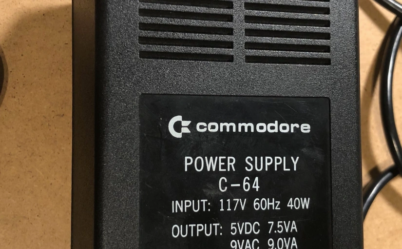
In my Commodore 64 Power Supply magic post, I talked about the internal power supply and how not everything that you see when you quickly glance is as obvious as it seems. Yet again I’m faced with a similar situation. I needed an external power supply for one of the machines that I purchased recently, and I didn’t want to pay almost the equivalent of half of the cost of the computer for a new power supply. I searched eBay and come across a “faulty, for parts” unit. Perfect for me, as I’ve got a small “lab” at home and I’m able to troubleshoot and hopefully fix it. It was the 902503-02 part number, that as opposed to some of the “newer” version is not “potted” and can be opened and inspected. Before the auction was over I was “researching” the power supply. My “research” started with googling “902503-02 schematic diagram”. The result brings a few similarly looking diagrams, but here is one of the first hits that I found:

Well, to me it doesn’t look like the original schematic diagram, it’s more of a reverse engineered diagram that someone has created looking at the real circuit of the power supply. We know roughly what to expect on the basis of what I covered in my previous post – two separate outputs: one is unregulated 9V AC, and regulated 5V DC. And at first glance, it sort of looks ok but in reality, this “diagram” is seriously misleading! Here is what I’ve noticed:

Let’s do the “simple” ones first: the diodes have some strange part numbers, in fact, those should be marked 1N5400. The “ground” symbol from the transformer goes nowhere, as there is only one of them. One of the outputs is marked 7.5A … 7.5A!!?? This should be corrected to 7.5VA – alternatively, the entire thing could be just marked 5V/1.5A. But the biggest and a major mistake is the “transistor” marked SK3052P. Yes, it’s a 3 legged device in a “TO-3P package” that looks like a transistor, but it would be impossible to create a 5V regulator based on a single transistor and a resistor. In fact, the “SK” in the part number is a logo for a Japanese company called “Sanken”, the full part number is “SI-3052P” – a 5V at 2A linear voltage regulator integrated circuit. So the author has done the following “mind shortcut”:

This is very unfortunate “shortcut” as I’ve seen a few posts on C64 forums where people are referring to that regulator as “transistor”! Well now you know it’s not, and the SI-3052P provides a few important functions: it regulates the output voltage at 5V DC independent of the load and it has a built-in overcurrent protection that will “kick in” when the load exceeds around 2.4A. Based on this new information and after “inspecting” one of those power supplies, I’ve re-created the diagram adding a few more details:
here is full resolution picture
Let me quickly describe what happens: mains voltage is supplied to the primary winding of our power transformer, notice the “protective earth” pin is somehow connected to the transformer (looks like it goes in the layer between the primary and secondary winding) but it doesn’t extend to the output and is not connected to the computer at all. There are two secondary windings:
- Pin 9 and 11: provides 9V AC that goes directly to the output. Its protected by a 3A fuse F1, I’ve marked the voltage rating of the fuse (250V) but this is not as important on the secondary side, what is important is to know if this fuse is a “slow” or “fast” acting fuse. Unfortunately, the fuse itself doesn’t have any markings saying what type of fuse it is. Inspecting it physically and considering its function I think it’s a “fast” acting fuse. You may ask why do we need this fuse, isn’t there another fuse inside the C64 that is on the 9V AC power rail. It’s true but the fuse here inside the power supply is supposed to protect the transformer form accidental shortcuts on the output before the power supply is even plugged into the computer.
- Pin 7 and 8: provides 18V AC with a “center” tab on pin 6. This center pin allows the use of two diodes in a full wave rectifier configuration, saving cost by not having to use a 4 diode full bridge rectifier configuration. Next follows a large smoothing filter capacitor C1. This part of the circuit is protected by 5A fuse F2, yet again there is no marking on the fuse, but considering it has to withstand a larger than standard operating conditions initial charging current of the smoothing capacitor and a clearly different physical appearance I deduct it’s the “slow” acting fuse type.
The unregulated voltage from C1 is regulated using U1, the SI-3052P integrated circuit. On the output of U1 we see an additional small electrolytic capacitor C2, that is recommended by the manufacturer to prevent oscillation. There is one more component, the 300 Ohm resistor R1, it’s used to “raise” the output voltage a bit over the nominal 5V to compensate for the losses on the long wires between the power supply and the computer. This is actually very surprising, as looking at the U1 datasheet, we see Note 3: “The output voltage may not be adjusted by raising the ground voltage (using a diode or resistor)”. This is related to the built-in “foldback overcurrent protection circuit” that will be affected if pin 3 of U1 is not at “ground level”. Looks like the engineers designing the power supply ignored the note. When I get a chance I will try to test and compare the behavior of the power supply in a fault condition, with and without that resistor.
Quick comment on the construction of the power supply. The diodes and fuses are soldered directly to the transformer “pins” (with the help of some additional internally unconnected pins 10 and 12). The rest of the components are mounted on a small printed circuit board (PCB). The transformer and the PCB are marked “Billion”, and I assume this is “contract” manufacturer Billion Electric Co., Ltd. of Taiwan, that Commodore tasked with the creation of this power supply.
Lastly, one should note this is a linear power supply, cheap but very inefficient. At full load (C64 plus accessories plugged into the expansion port drawing in total around 1.4), the input voltage on U1 is over 10V, so to “drop” the voltage to 5V on the output the linear regulator has to dissipate close to 8W of power (voltage on input minus voltage on output multiplied by current). U1 and its heatsink get extremely hot, and as we know, hot semiconductors don’t last long…
In part 2, I will cover the restoration/repair of my eBay purchased power supply, I will share some test results and implement few improvements… stay tuned.

great article, just one point, a slow blow fuse generally has a small spring inside, where as a fast blow will be a straight piece of fusible wire, some designs also have a small resistor in the fuse itself
LikeLiked by 1 person
Thanks Karl. Totally agree with you on the fuse description, and this is why I “assumed” F2 is slow (it has a bit of spiral/spring shape” and F1 is fast, as it’s just a wire.
LikeLike
I came across your articles be chance. Really great. Tey are really helpfull to me.
I’m messing around with a c64 psu to rebuild it in a bigger case and add a “saver” to it and a display with amp and voltage in the 5v rail if possible. I was wondering a few things:
First: How about using just the “+9” part of the output transformer to the 5v rail and a complete 4 diode bridge? Would it be the same and provide enough power(both volts and amps) to the 7804 (mine has one of those instead of the one her mentioned)? If so, what should done with the negative transformer output? Just leave it unconnected?
The idea is for the 7805 not having to disspipate so much non used power.
Second: there are a few dc-dc converters that could be used instead of the regulator, but I’m not sure if they are a real improvement, since the c64 is a little too delicate machine. I understand these dc-dc converters are just like a little switching PSU themselves, but as my knowledge of electronics are not much, I’m not sure of that. But maybe it’s a test you may like to try. The cheap ones I’ve seen have a rated switching of 340 kHz. I guess it would be recomended to introduce some capacitors to soften the output and make it really continuous. Those for example:
https://es.aliexpress.com/item/4001291204998.html?spm=a2g0o.productlist.0.0.5f5f48ffEzLFbF&algo_pvid=d2de96c6-2e5e-48b0-b902-867f1cfee037&algo_expid=d2de96c6-2e5e-48b0-b902-867f1cfee037-0&btsid=0b8b036d15993302091282402ee21c&ws_ab_test=searchweb0_0,searchweb201602_,searchweb201603_
https://es.aliexpress.com/item/4001224962132.html?spm=a2g0o.detail.0.0.1b4b10c0669OFc&gps-id=pcDetailFavMayLike&scm=1007.12873.140318.0&scm_id=1007.12873.140318.0&scm-url=1007.12873.140318.0&pvid=d5ec50ae-d5fc-4a78-8712-f5ae28aef2ca&_t=gps-id:pcDetailFavMayLike,scm-url:1007.12873.140318.0,pvid:d5ec50ae-d5fc-4a78-8712-f5ae28aef2ca,tpp_buckets:668%230%23131923%2379_668%23808%233772%23811_668%23888%233325%239_668%232846%238116%23986_668%232717%237564%23691__668%233374%2315176%23303
Third: my power supply has a capacitor that is not an electrolitic, but hs polarity. Can it be replaced by an electrolitic one? Why is it not and what kind of capacitor is it?
Mine looks more like the one in the link above, but with the center pin output transformer and 2 diodes of yours. It’s a white c64c PSU block.
Thank you for your articles.
LikeLike
Hi Antonio, thanks for the comment. Here are some answers. 1: You can not use the AC 9V to power any of the DC 5V circuit. The reason is they have to be completely galvanically separated as the AC 9V is later used to generate 12V DC inside the C64 (see my other article about the internal power supply). 2: The DC-DC converters are definitely the way to go, hey waste much less power in comparison with 7805, the trick is to find a good quality DC-DC converter otherwise you risk sending a over voltage to you c64 (since you are planning to add a “saver” to the circuit it’s probably ok. I personally use a high quality DC-DC converters from Murata OKI-78 series. 3: It should be ok to replace the non electrolytic capacitor with electrolytic (it’s probably a tantalum capacitor btw). Watch out when you use the DC-DC converter you may have to put some good quality capacitors that have to be adjusted to filter out the switching nose. Good luck with your project!
LikeLike
Thank you for your answer.
“Watch out when you use the DC-DC converter you may have to put some good quality capacitors that have to be adjusted to filter out the switching nose.” I was afraid it has to be so.
Someone told me that when needing more amperage out of a regulator (7805) he had used two in parallel. With such a high input voltage for the regulator in our PSUs, will this be a solution to divide the power dissipation and will they be working cooler individually?
Are the older PSUs with two 9v ac outputs in the transformers running cooler than this 2 diodes one?
Thank again.
LikeLike
In theory it sounds like a good idea, but in practice you it will never work well. You would have to find a pair of 7805 with exact same outpout voltage (I know they are all outputing 5V, but you would need two that match exactly 5.000V). Otherwise you end up with all sort of issues where one of them is loaded more than the other, and the regulators will “fight” to get the output voltage match their own reference, you will end up with unstable power supply… in conclusion – bad idea 🙂 I would suggest focusing on a switched module power supply (either a DC-DC coverter or a AC-DC switch mode power supply module, and just use a transformer for the 9V AC output).
LikeLike
Hi Antonio, i think that Primary circuit (pin 9, 11) and secondary circuit (pin 6,7,8) are galvanically separated. I tested the resistance between pin 9 to pin 6,7,8 and between pin 11 to pin 6,7,8 using a multimeter with result of an infinite value. I’m making a circuit, getting 9VAC from secondary, to have 5VDC as your schematic.
LikeLike
I also forgot to ask… If using a dc-dc converter, can the voltage be slightly increased with the resistors in the ground pin?
LikeLike
nope, don’t just randomly add a resistor… it’s better to get a DC-DC converter with adjustable output (or follow the DC-DC converter chip datasheet to figure out how to adjust the output voltage)
LikeLike
In my original PSU there’s a capacitor (2200nF) between pin 1 and 2 of the 7804 (and so the joint of the two resistors that a increase the output volume). What’s it for?
LikeLike
The 2.2 uF capacitor is recommended in 7805 implementations and is meant to “improve transient response”, check datasheet for more information.
LikeLike
Thank you. You are being a great help for me.
LikeLike
Another crazy idea. What about keeping the circuit as is but with a higher voltage regulator, and then adding and additional dc-dc converter at the output? The regulator could be a 7809 or 7808 one. after the dc-dc there should be any filtering capacitor anyway.
LikeLike
That is a crazy idea Antonio 🙂 You’ve been asking many questions, but I still don’t fully understand what are you trying to do. The replacement power supply for c64 is an “old” idea, there are many good designs around, even ready-made good replacement PSUs can be easy purchased on eBay … but coming back to your question, this would not make sense, most DC-DC converters will accept wide range of input voltage and due to the efficiency (sometimes over 95%) they will generate very little heat, so this is a good way to go. What you could do and it would work probably quite well is to put a DC-DC converter fist and follow it with a linear regulator – this way you “step-down” the voltage to the minimum required by the 7805 and have the benefit of noise-free linear regulator output 5V… the only issue is that typically 7805 will need at least 8V input and at 1A of current going to you c64 you will still have to dissipate 8V-5V=3V*1A=3W of power… I say a good quality DC-DC converter is the best way to go, alternatively use a standard 7805 but with a decent size heatsink.
LikeLike
Very interesting! I’d love to read the part 2, if you ever get a chance to write it. I realize how much time goes into writing these kind of posts, tho.
LikeLike
Hi Jerri, thanks for reading my article and taking the time to leave a comment. Wow, can’t believe I wrote this in 2018! I actually finished the project and have a bunch of material ready for the 2nd part… just struggling to find time to do it, but comments like yours are a good motivator so… “watch this space” 🙂
LikeLike
Hello there….. we are waiting for part 2…. when?
LikeLike