
As always, all source code and design documents are on my github page: EPROM-EMU-NG on GitHub
I recently posted an article that shows how people ended up using the emulator, check it out there: EPROM emulator NG use cases.
EPROM EMULATOR – An Introduction.
Well, before I explain what an EPROM Emulator is, I should first explain what an EPROM is. EPROM or Erasable Programmable Read-Only Memory is a type of programmable read-only memory that is used to store programs in “computers”. And when I say “computers” I refer to the 80s eight-bit machines (Commodore, Amiga ZX Spectrum, Tandy etc.), but also other computer like devices, controllers etc. that require program memory. Those EPROMS typically come as ICs in DIP28 package with a “window” in the middle used to “erase” the memory using UV light. See below:

So, what is the issue and why would one need an EPROM emulator. By its nature, this type of memory is “read-only” and to change its content you need to erase it with UV light. Imagine you are developing software (well, firmware more likely) and you need to change the “program” in your EPROM memory. That means, remove the EPROM from its host computer, subject it to 20-30min of UV light exposure, program it with EPROM programmer, re-install in host computer. The entire process is extremely slow and has to be repeated every time you want to make even a small one-bit change! And yes, there are modern EPROM alternatives based on Flash technology, that could save you the 20-30 min erase time, but the rest of the process is still the same and still annoyingly slow if you’re writing code and trying to “debug” it.
This is where the EPROM emulator comes in handy, a device that can temporarily “replace” your EPROM chip, it is controlled by a computer and can be reprogrammed in seconds. Once you finish testing you can replace the emulator with an EPROM chip programmed with the final version of your code.
My “EPROM EMULATOR NG” – the “what”.
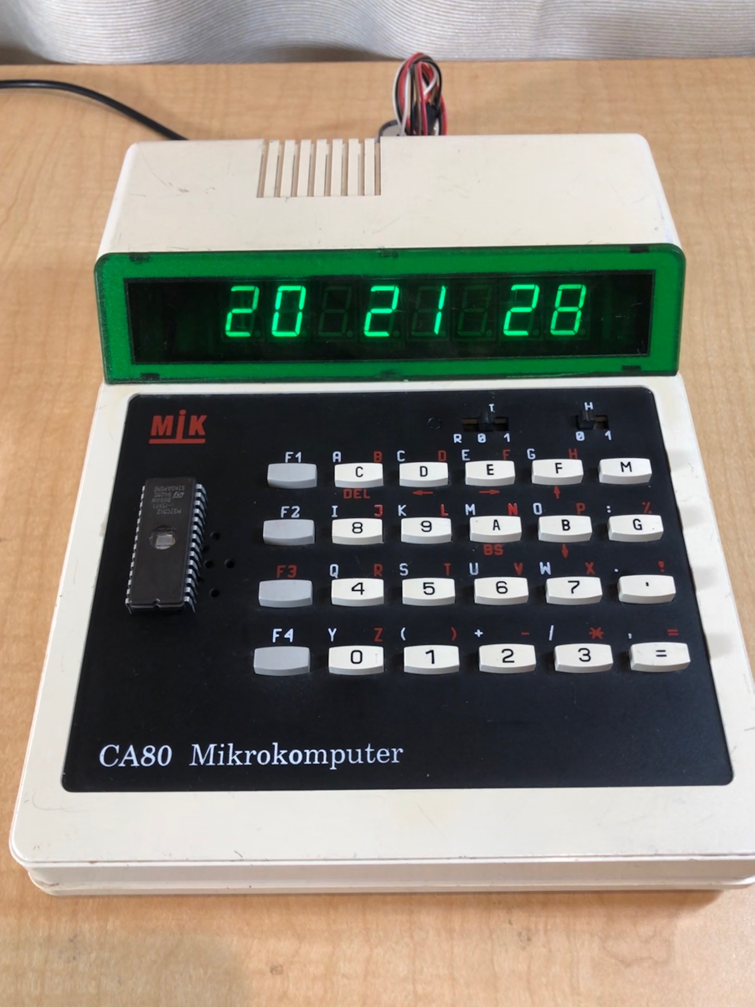
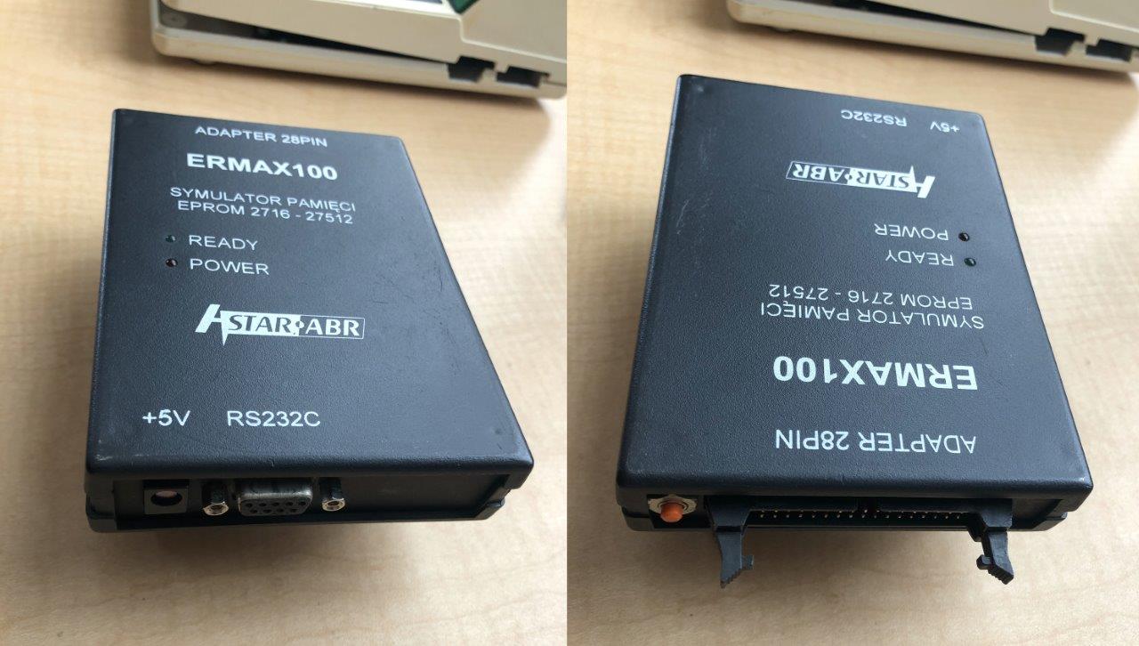
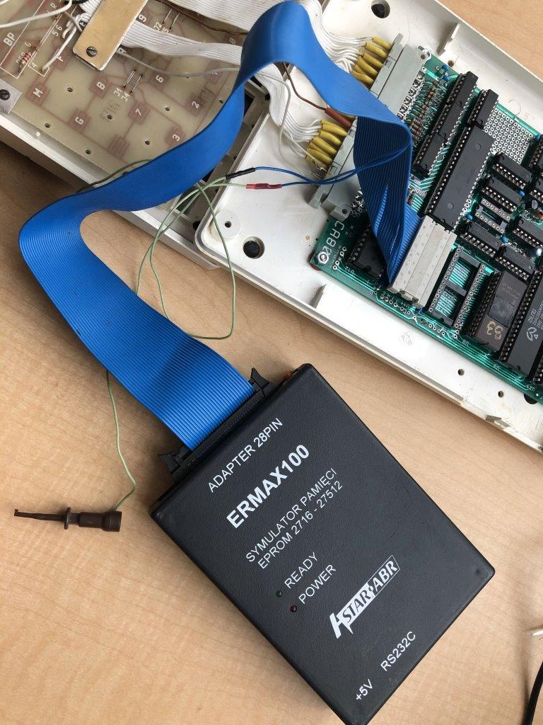
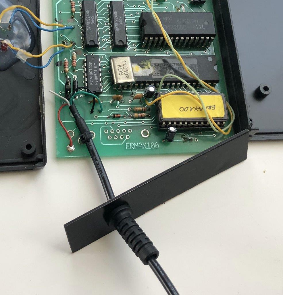
Those who follow my blog know that I already have a commercial EPROM emulator (see the ERMAX100 EPROM Emulator Revival post). I have been using it extensively recently and only just discovered a few really annoying “features” of that emulator. So I was motivated to create something similar to ERMAX 100, but based on a modern microcontroller platform, open-source, cross-platform control software, and free of annoying limitations of my old device (more on that later).
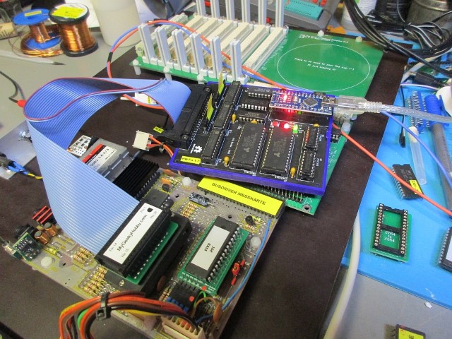
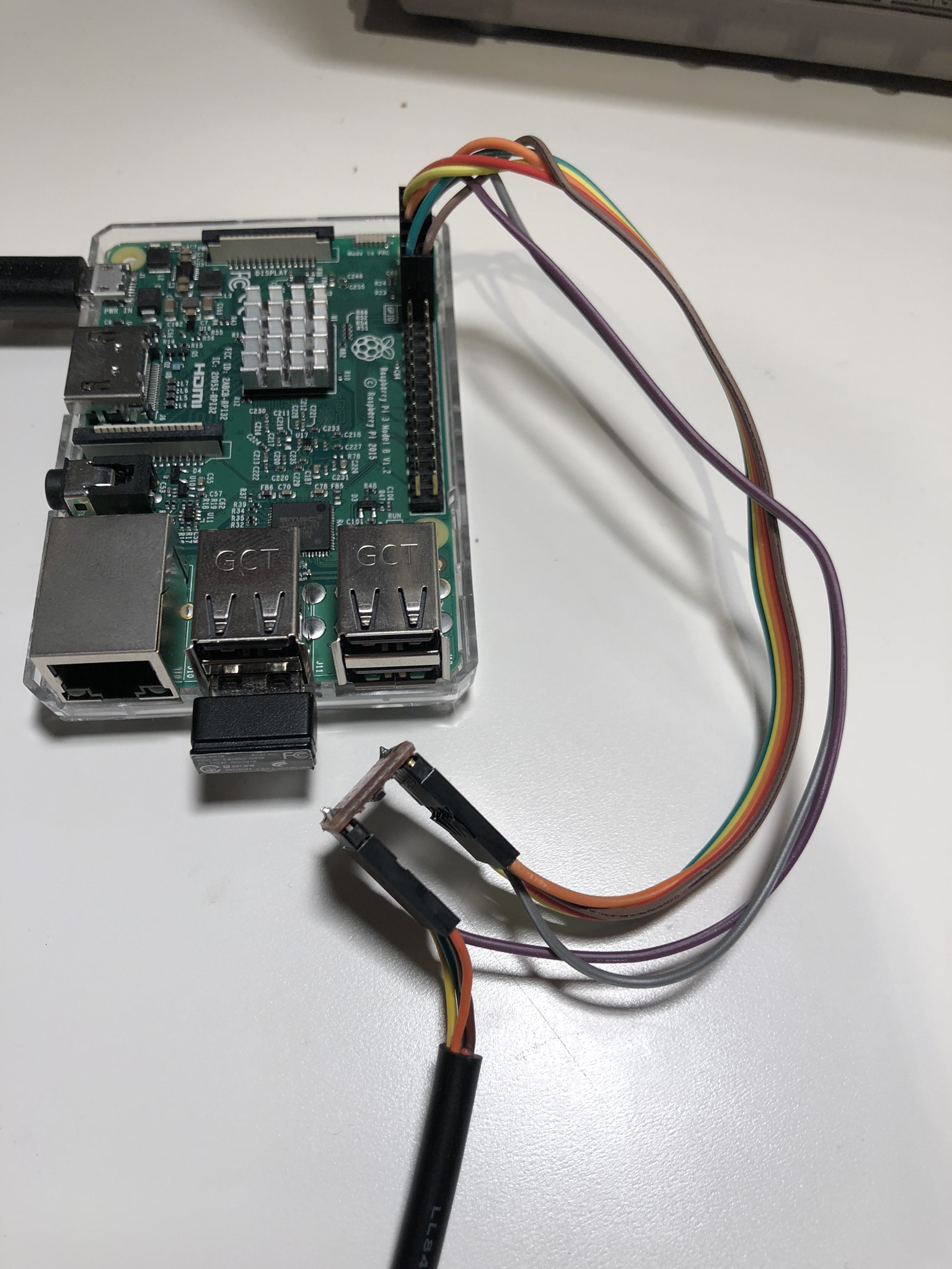
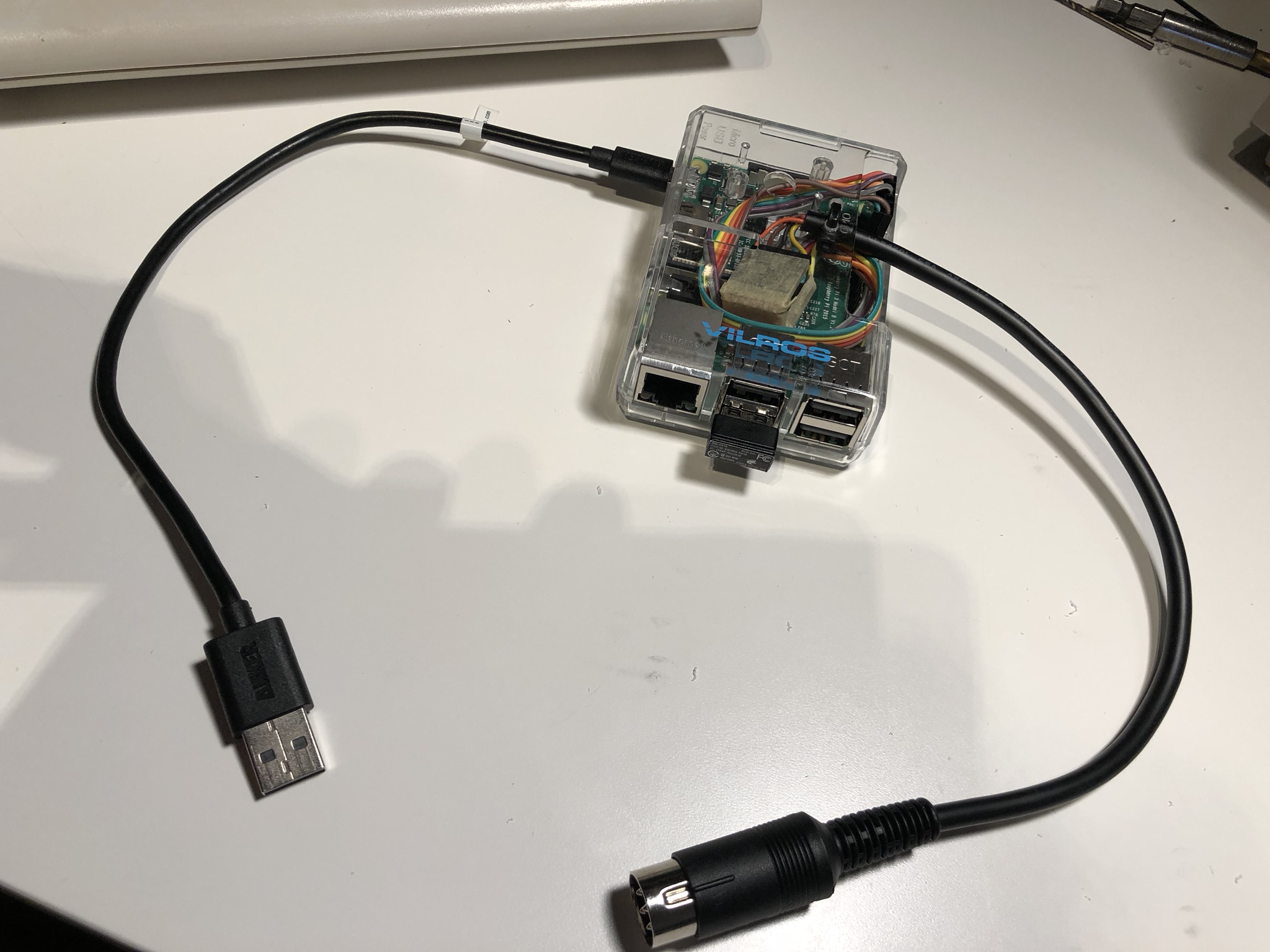
Let’s first have a look at the final result:

On one end the Emulator has an IDC34 connector J1, where you can plug a DIP28 “probe”, this probe replaces your EPROM device. The probe cable also has two “clips” carrying “reset” signals so you can restart the target platform once new code is uploaded to the emulator. On the “other end” we have a USB (mini in this case) socket allowing connection to the host computer that will control the emulator. The software that controls the emulator is written in Python (3.8) and so far, I have tested it on both Windows and Linux (raspbian) platforms, but should also be compatible with macOS, all basic features are already implemented, but since it’s all open source you can add any other feature you can think of.
The “brain” of the emulator is the Arduino Nano module, the sketch provided in the GitHub repository has most of the features I could think of already implemented. I’m not strong in “C” programming, in fact, the Arduino firmware was based on another project by fellow geek Natasza (check out her memory loader project). It was a good starting point for my implementation, but there is loads of scope for future “improvements”.
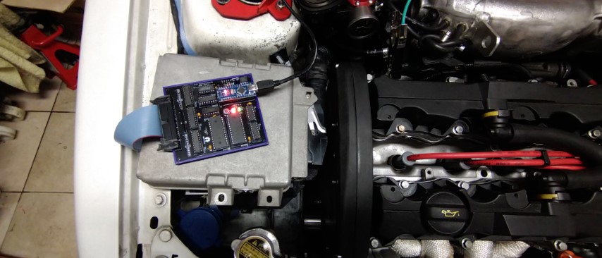
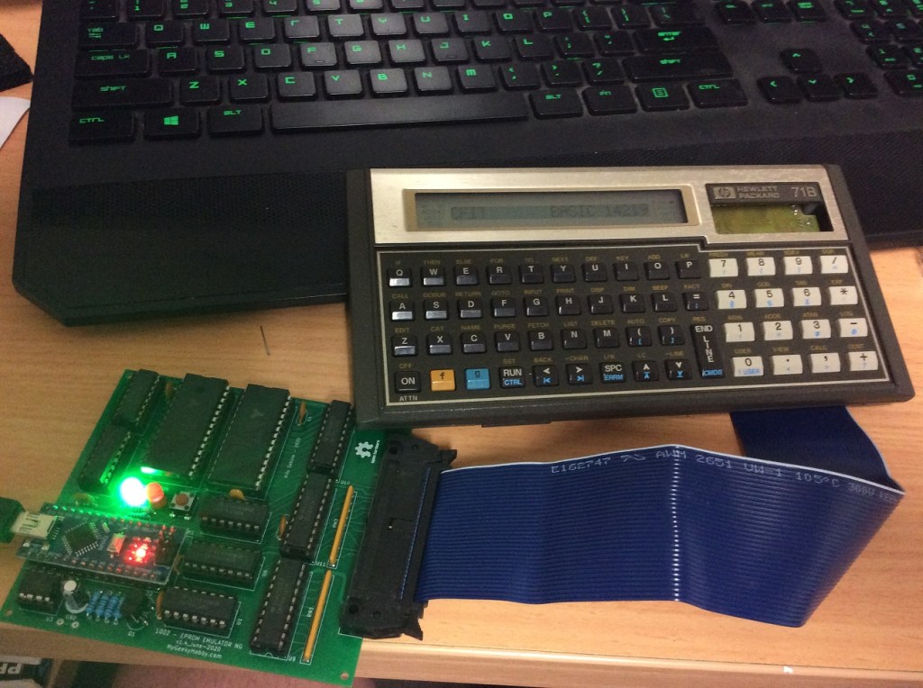
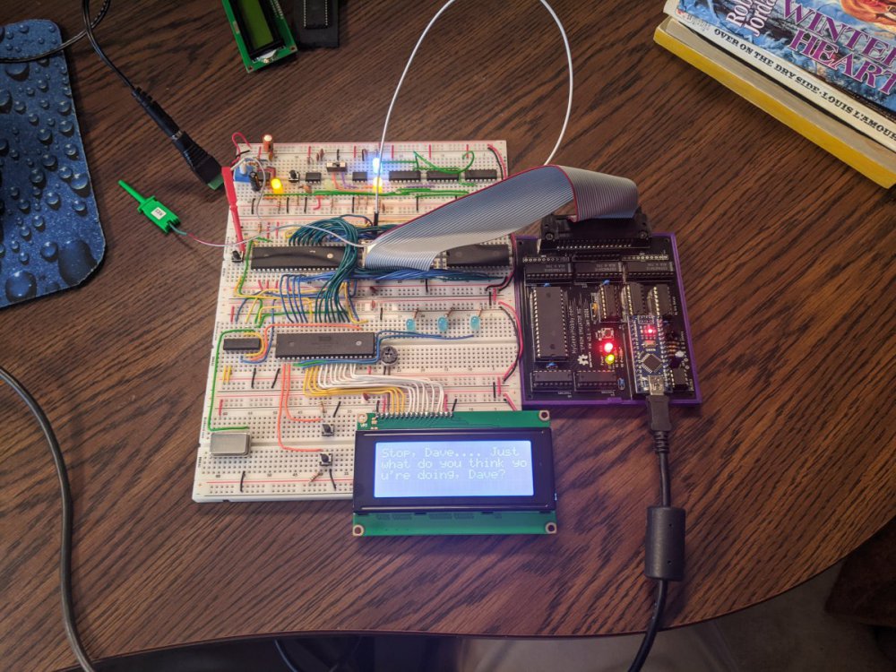
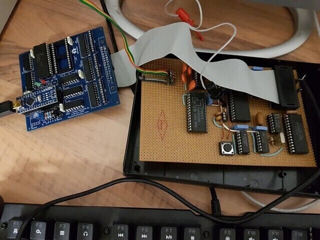
Let’s take a look at some examples of how I use the emulator.


My “EPROM EMULATOR NG” – the “how”.
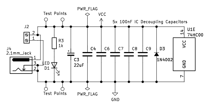
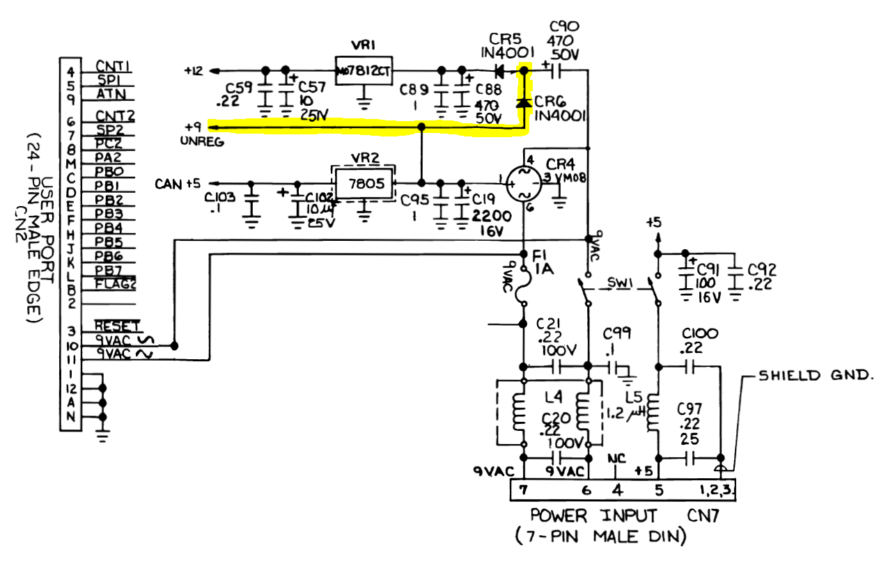
Now we can look into some of the design details, let’s start with the schematic diagram.

There are a few building blocks of the device:
M1 – the Arduino Nano, the “brain” of our emulator – cheap and easy to get. Well-known and supported in Arduino IDE.
U7 and U8 are 32kB static RAM devices (SRAM), together with gate U1B they provide 64kB memory space that will be used to “pretend” or “emulate” the maximum supported 27C512 EPROM. Why am I not using a single SRAM of 64kB capacity you might ask? Those are hard to get today as 64kB SRAM was not very common. In fact, I had quite a few of the 62256 memory ICs spare, plus you can still find this type of memory on Digikey so I decided to stick to those. Why I didn’t use a Flash-based memory instead, well that is a longer story, but I really wanted to just “improve” an existing design of my commercial emulator, and initially didn’t care about the fact the SRAM memory will be cleared when power is gone.
J1 is the connector where we DIP28 “probe” is connected. Details on how to build one of those are also in the GitHub repository.
U9-U11 are 3 state 8-bit buffers, that allow us to “disconnect” the emulator from the target device/machine while we re-program the SRAM.
U4-U6 are serial to parallel “converters” (shift registers) that allow us to generate the Data (8 bit) and Address signals (16 bits) required to control the SRAM, all this using only 6 lines of the microcontroller. Important to note, they have a 3 state output, allowing us to “disable” them from the SRAM bus when the emulator is “running”. Note how the only pin that is unique to each of the shift registers is the data pin, all the other pins are connected in parallel (SRCLK, RCLK, OE etc). This is an unusual configuration, but it allows us to simplify the main routine that shifts the data into the chips, the main loop only needs to do 8 iterations to load all 24 bits (8 of data and 16 of address).
// Write single byte of data to SRAM

void writeMemoryLocation (unsigned short address, unsigned char data ) {
    unsigned char addressHi =  address >> 8 ;
    unsigned char addressLo = address & 0xFF ;
    unsigned char memData =  data ;

    // send data

    for (int i = 0; i < 8 ; i++ ) {
      digitalWrite( DATA, 0x80 & (memData << i) );
      digitalWrite( ADLO, 0x80 & (addressLo << i));
      digitalWrite( ADHI, 0x80 & (addressHi << i) );

      digitalWrite( SCLK, HIGH );
      digitalWrite( SCLK, LOW );
    }

    digitalWrite( DAT_LD, HIGH ); // latch data and address out
    digitalWrite( DAT_LD, LOW );

    // at this point we have data and address loaded into the shift registers
    // now we can request a write to SRAM memory

    digitalWrite( WE, LOW );
    digitalWrite( WE, HIGH );
}
Gates U2A-U2D and U1A allow a to “selectively ignore” address lines A11-A15. Why? Imagine a situation, where you would like to emulate for example a 2764 EPROM, you want to make sure address lines A13, A14 and A15 are ignored in that case, regardless of how they are connected externally to the emulator. This was a major issue for my ERMAX emulator, I was at the “mercy” of how the target EPROM socket was wired in the design. Sometimes even if the device was using a small 27128 EPROM, A15 line would be at VCC (Logic high) so I had to re-map my program to match etc. This new design fixes the issue.
Optional block with the 64kB SPI EEPROM U3 and push-button SW1, was a “design evolution”. Initially, I didn’t care about what happens with the emulator when the power goes “off” – so you lose the “uploaded” image and you have to re-upload when the power comes back “on”. Not an issue when you are writing and debugging your code. But later I realized the EPROM Emulator could be used as a “virtual cartridge” for my Commodore 64, so “restoring” the state of SRAM on power “on” would be useful. I had a choice to totally re-design with Flash-based memory or a simple “hack” by adding the SPI EEPROM and since the SPI EEPROM is also very well supported in Arduino IDE plus I had the required “spare” pins on the microcontroller I decided to go the SPI route. PC control software allows you to decide if you want to upload to SRAM and save to SPI or just upload to SRAM. You also get a choice if you want to “automatically” restore the SRAM from SPI EEPROM on “power on”.
Diode D5 and fuse F1, is a minimal “power management”. The device can be powered by USB-generated 5V from the Arduino Nano or from the DIP28 target device. D5 prevents powering the target from the Arduino, the fuse limits the current drawn from the target if something goes wrong. The diode also protects the emulator from accidentally plugging the DIP28 probe the “wrong way around” into the target. There is some voltage drop on both of those elements. In certain situations, you may want to skip or bypass those. I’m keeping both of them in my emulator and haven’t yet seen issues – but at this point, my design is not widely used so I can’t comment further.
“EPROM EMULATOR NG” – I want one.
So you think it’s a useful device and you would like to own one? You will need to build the hardware first. For that, you should start by getting the PCB. All design files are in my GitHub repository and you can order the PCBs from one of the Chinese prototype houses, I used PCBway and if you don’t have an account yet, you can help me by signing up to PCBWay using my referral link:

(this will give me a few $ credit for my next project and you will also get a few $ towards your order in return). .
Once you sign up to PCBway, order the project PCB using this link:
And here is a link to DigiKey cart for PCB hw ver 2.2d, but due to chip shortage quite a few components are out of stock, and here is a cart for hw 1.9d, both include all components required to build the emulator and the probe. The cart total is around $60, you may consider sourcing the Arduino and the flat ribbon cable elsewhere. Other components in the cart are in quantities needed to build a single emulator – but remember you will get 5 PCBs from your order, so might be worth increasing the quantities to build 2 or more :). Also, since you are already paying for the delivery, increase the numbers on some of the common components (one can never have enough decoupling 100nF capacitors).
If you don’t want to build it yourself, I will have some of those devices listed on eBay, including parts “kits” and PCBs:

Once the hardware is built, the rest is just Arduino firmware and python control software, both can be found on my Github page.
As of October 2020, I’ve had reports from many people who successfully built and are now using the emulator. I recorded a quick introduction video that covers the basics of usage. Check out my YouTube channel:
For those planning to build or buy one of my ready devices, I’ve set up a group on groups.io where we can collaborate, feel free to join: https://groups.io/g/eprom-emu-ng
Last note: most of the pictures you see in the above description is v1.0 of the PCB. I built the first 5 prototypes and later discovered an issue with the PCB layout, one of the shift registers (U11) was getting onto a CMOS latch-up state, even though I had a few bypass caps around the PCB, I was still occasionally getting the issues. I fixed my prototypes with a few “bodge” cables.
I improved the PCB design, re-routed some of the power connections and repositioned some of the components, and released as v1.4. At this point the project evolved even further, so what you see on GitHub is PCB v2.1! In the most recent change, I moved from using two smaller SRAM memory chips to using a single larger one. Firmware and software stay the same for both versions.
If you found this helpful and you like the work I do, why not buy me a coffee, thanks! 🙂


