
This article is mainly aimed at my Polish readers, owners of the educational computer CA80, but the i2c bit-banging for Z80+8255A may come useful on other Z80 platforms. As always source code can be found on my GitHub page.
8255 port control challenge.
There are many websites that cover i2c in detail, so I’m not going to spend any time doing that here, but in the context of this article, the key issue is the fact I’m trying to use a very basic “software-only” implementation of i2c – later used to pull date and time information from hardware real-time clock (HW RTC). I2c uses two lines to implement it’s the bus: SDA (for data) and SCL (for clock). Those two lines have to be independently controlled via software, additionally, SDA is bi-directional, sometimes used as output and sometimes as input. The 8255 offers 3 ports (A, B, C) of 8 lines of general-purpose I/O connectivity. Unfortunately, the way it operates, all lines of each port can only be configured as input or output all at the same time. So if we “plug” our SDA and SCL lines to the same port (for example port B lines 0 and 1), we would not be able to implement the i2c bus this way. The only solution is to use two independent ports (for example port A, and B, or A and C). One more “trick” you can use is the fact that port C, is actually split in half and can be controlled independently (port 0-3 in one group, and 4-7 in another). This is exactly what I’ve done. Let’s see the diagram:

As you can see, I’ve used PC.0 for SDA and PC.4 for SCL signals. R1 and R2 are pull-up resistors (I used 10k, but 4.7k would be ok as well) required for all implementation of i2c, R3 and R4 are used for current limiting, for situations where software might be misbehaving sending data at the same time other transmissions are in progress. In my example I’m communicating with a popular RTC from Dallas – DS1308Z (you can use a cheap module from eBay – be aware of issues with those modules where the “trickle charge” circuit may cause the re-chargeable 2032 battery to explode. This has happened to my module, so I removed all the extra components, and I used a non-rechargeable 2032 battery).
The GitHub repository contains the required code RTC_0x2000_0x2300_v1.4.asm The file contains a read and write procedures for the RTC. The code is a bit of a mess of stuff I found on other projects and my own code – but since I haven’t done Z80 assembly language for the last 20 years there is much scope for improvement. Feel free to contribute, but in its current form, the program works and serves its purpose 🙂
The next section is more useful to my Polish audience, so I’ll attempt to write it in Polish.
Dla polskich użytkowników Mikrokomputera CA80 firmy MIK.
Niedawno udało mi się „reanimować” mój emulator pamięci EPROM ERMAX100, wiec w końcu mogę zabrać się ze parę projektów na CA80 które odwlekałem przez prawie …. 20lat.
CA80 to był prawdziwie mój pierwszy…hmm “komputer?”. Poskładałem go jeszcze w podstawówce! I działał. Powstało kilka projektów, pamiętam dobre czasy pisania programów na kartce papieru i „kompilacji” z książką w ręku, oraz żmudne wklepywanie kodu przez klawiaturę CA80.
Dziś, mój CA80 rzadko jest używany (chociaż teraz gdy mam możliwość łatwej emulacji EPROM, mam nadzieję ze to się zmieni). Większość czasu spędza na moim biurku, wyświetlając „CA80”. Dobrze by było chociaż na co dzień używać go jako taki „retro” zegar. Ja mam nową wersje komputera z wyświetlaczem VFD. Niestety brak podtrzymania pamięci czy sprzętowego zegara czasu rzeczywistego (HW RTC) bardzo ogranicza CA80 w funkcji zegara. W tym projekcie chciałem uzyskać następującą funkcjonalność:
- Zegar „tyka” gdy brak zasilania – aka HW RTC na magistrali i2c z potrzymaniem bateryjnym.
- CA80 automatycznie wyświetla czas gdy zasilanie powróci (komenda *E[0] startuje automatycznie).
Postanowiłem i2c zrobić w programie, poprzez tak zwane „bit banging”. Elektronika to tylko podstawowe elementy standardowej implantacji DS1307Z (gotowy moduł można kupić na eBay za parę dolarów).
Kod źródłowy programu jest na GitHub. Plik RTC_0x2000_0x2300_v1.4.asm należy skompilować darmowym „z80-asm” asemblerem. Jest zaprojektowany by został zaprogramowany do EPROM w podstawce U9 CA80, zaraz ponad podstawowym kodem pod adresem 0x2000h. Ja miałem w U9 pamięć 2764, którą wymieniłem na 27128.
Aby uzyskać automatyczna synchronizację po starcie oraz automatyczne wyświetlenie czasu, należy też zastąpić komendę skoku do głównego menu w monitorze CA80, skokiem do mojego programu:
Pod addresem 0x0269h zamienić komendę:
JR START ( 18 05 )
na:
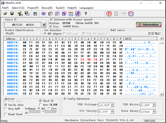
JP 2000h ( C3 00 20)
Na GitHub zamieściłem obraz binarny dla pamięci EPROM 27128 oraz 27256 który zawiera już dodatkowy kod i zmiany w monitorze, należy tylko go zaprogramować i zainstalować w CA80 w podstawce U9 (zakładam ze wszystkie połączenia konfiguracyjne są w fabrycznej pozycji). Elektronikę można zlutować na wewnątrz CA80 lub podłączyć do złącza użytkownika, wymaga tylko 4 połączeń (VCC,GND, SDA-PC.0 i SCL-PC.4).
Program automatycznie odczyta czas i datę po starcie CA80 z HW RTC and nastepnie automatycznie przejedzie do wyświetlania czasu. Wszytkie inne zlecenia powinny działać bez zmian. Do monitora można wrócić naciskając klawisz “M”.
Żeby zaprogramować aktualy czas do nowego układu RTC, należy najpierw ustawić czas w CA80 zleceniem *E[1][sek].[min].[godz]= a następnie wywołać program użytkownika pod adresem 0x2100h komendą *E[G][2100]=, która zapisze aktualny czas do HW RTC.
Kod jest napisany tak “na szybko”, część jest skopiowana z innych projektów online, wyszedłem z wprawy nie pisząc w assembly prze 20lat 🙂 Zapraszam do ulepszenia.
Tymczasem zostawiam was ze zdjęciem mojego CA80, dumnie wyświetlającego czas.

