
Note:
At the beginning of this post, I cover some basic power supply stuff, so if you already know a lot skip to the later part where I cover the more interesting 12V DC rail.
Not as obvious as it seems.
While browsing “SAMS Commodore 64 Troubleshooting & Repair Guide” I came across the block diagram of the internal power supply system. It was interesting to me for a number of reasons. First, I’m “into” Commodore restorations those days so this generic knowledge is useful, also I hoping to develop a DC only power supply (so that you could run the C64 off of a 12V car power socket). As a reminder this is the block diagram that I’m talking about, from the book:

Something wasn’t right here… notice the diode on the +9V supply line. My background is electronics, but even though let’s just say I haven’t “practiced” for a while, the direction of that diode makes no sense, it wouldn’t work. Let’s look at the detail diagram from the C64 service manual:
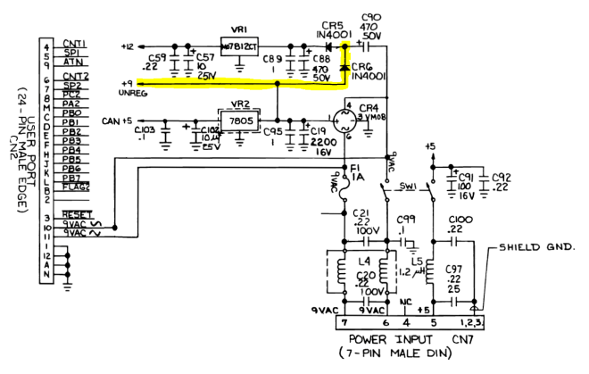
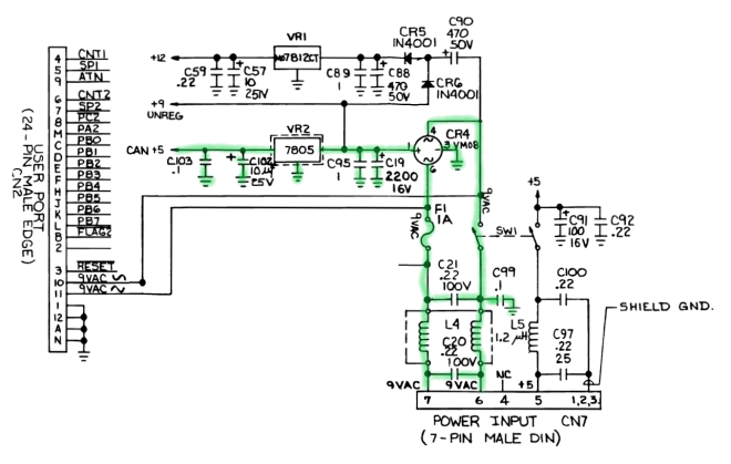
Looks familiar? I’ve highlighted the section that I’m wondering about. Seem like the authors of the troubleshooting guide have made a mistake when creating the block diagram, in fact, the diode CR6 (1N4001) has nothing to do with the unregulated +9V power supply line. Since we are already discussing details of the power supply diagram let’s analyze all sections and how each of the power rails is generated one by one:
9V AC

The 9V AC power is supplied from the external power supply, passes via a common mode choke filter and a fuse. It is then used to generate all other rails plus is made available on the user port pins 10 and 11. Important to note is that the 9V AC rail is also used to generate the 60Hz/50Hz signal for the hardware real time clock built into the CIA chip. This is one of the reasons we can’t replace the external power supply with a modern DC switch mode alternative.
5V DC (+digital)

Just like the 9V AC, the 5V DC is supplied from the external power supply, it’s filtered and used directly to power majority of the “chips” on-board. Important: since there are no additional components onboard of the c64 handling the 5V DC digital rail, you’re at the mercy of the quality of the external power supply – and we know those old original power supplies are failing a lot. Typically they fail with an over-voltage condition, resulting in “fried” memory and other components, so always check the condition of the external power supply before you use it for the first time.
5V DC CAN (Clock and ANalog ??)
You may ask yourself why do we need another 5V DC rail, we already have one from the external power supply. Separate, locally generated power is needed for the sensitive video and clock circuits of the computer. The configuration is “textbook” implementation of the 7805 regulator IC. The 9V AC is rectified using bridge rectifier CR4, smoothed using large electrolytic capacitor C19, decoupling capacitor C95 before getting into the regulator. Regulator output is decoupled with C102 and C103.
12V DC
Now we come to the interesting part of my article.

At first glance, you see the 7812 regulator, some bypass components around it (c59, C57, C89, C88) and fed from the 9VAC. But look closely and you see 3 extra components that are not instantly recognized by most: diodes CR6, CR5 and capacitor C90. What are those for? When I first noticed those I came to the conclusion that it must be used to boost the unregulated voltage coming out of the bridge rectifier CR4 and smoothing capacitor C19 to a level required for correct operation of the 7812 regulator – that is typically around 14.6V DC. What I could see from the diagram was:
- clamper that consists of capacitor C90 and diode CR6, one should note that in our case this is a “biased clamper” type, as the anode of diode CR6 is not connected to ground but to the 9V unregulated dc supply.
- peak detector (aka half-wave rectifier) that consists of diode CR5, followed by a smoothing capacitor C88.
Ignoring the fact that we are dealing with “biased clamper”, this combination of clamper and rectifier is a typical example of the voltage doubler.
I started “poking” around my Commodore with an oscilloscope (all captures are with 5V / division setting).

Higher resolution picture here. (btw one day I will learn how to implement a proper gallery in my posts).
Looking at the oscilloscope we see the AC supply entering C90 (bottom right). The amplitude is around 12V, but we can’t fail to notice we only see the positive half of the “AC” signal. This is due to the fact that we are measuring this in reference to the power supply ground, so one of the diodes of CR4 bridge rectifier is forming a half-wave rectifier.
The output from C90 can be seen in the top right and is “shifted” from the ground by the level of “biasing” voltage, in our case, it’s around 10V DC.
Finally, we can see what happens after our supply goes through the half-wave rectifier CR5 and smoothing capacitor C88. Note the output DC voltage that is present on C88 is over 20V. That means that C88 must be rated at 25V minimum. I mention that as I’ve seen people commenting that when “re-capping” capacitors on board of the Commodore you can stick to 16V rated electrolytic capacitors – as you can see this is not true.
All this “complications” mean that it’s not easy to replace the external power supply with a simpler DC switching power supply. Without modifying the internals of your Commodore you will need both DC 5V digital rail and separate 9V AC rail.
Final thoughts.
I hope this was informative. Note that what I described above is what I think is happening, and I’m around 95% sure, but feel free to comment if you think I’m wrong and I will fix it.
I’m working on more Commodore related “material”, so more will follow.
